Page 4 of 7
Re: Punchy21's Controller Diagram for the CSVC

Posted:
Mon Apr 22, 2013 9:15 pmby punchy21
Canadoz wrote:Canadoz wrote:BackyardBrewer wrote:Great looking box!
Thanks mate couldn't have done it without your design.
:handgestures-thumbupleft:
Don't know why I thought you were Punchy......
It's ok we look the same... :wtf:
Nice work by the way too... It's not my design, I just made the pic. :handgestures-thumbupleft:
Re: Punchy21's Controller Diagram for the CSVC
Posted:
Mon Apr 22, 2013 10:15 pmby Canadoz
punchy21 wrote:Canadoz wrote:Canadoz wrote:BackyardBrewer wrote:Great looking box!
Thanks mate couldn't have done it without your design.
:handgestures-thumbupleft:
Don't know why I thought you were Punchy......
It's ok we look the same... :wtf:
Nice work by the way too... It's not my design, I just made the pic. :handgestures-thumbupleft:
Thanks mate, and thanks anyway. even if only for the pic. :handgestures-thumbupleft:
Re: Punchy21's Controller Diagram for the CSVC
Posted:
Sun May 05, 2013 9:51 pmby punchy21
A quick vid of a PSR25 going through its range. Shit do I sound like that... :wtf:
http://youtu.be/h7ODFxr6MOg
Re: Punchy21's Controller Diagram for the CSVC
Posted:
Mon May 06, 2013 1:11 amby Brendan
Thanks for the vid punchy :handgestures-thumbupleft:
It might be getting a bit technical for most to worry about, but my query before was on the SSR's being used which work on a zero-crossing, whereas the PSR is a phase angle controller...zero crossing is completely useless on applications requiring phase angle control (fine tuning severely suffers), but we seem to get away with it with heating elements...had just heard of a few only getting half the range of control (using the Fotek SSR-40VA).
Always good to see a controller in action though :D
Re: Punchy21's Controller Diagram for the CSVC
Posted:
Wed May 08, 2013 12:48 amby Tim
Thanks Punchy, I have also looked into the SSD and it seems to work as the data sheet states, have you had any issues with heat transfer between the heatsink and the unit? Have you had any units fail due to heat overrun? Are you using heatsink compound (only asking this so that people USE heatsink compound)?
As I think I will be going down the same route as you have ... great idea! ... I will be running 2 x 2400w elements with the 25A module .
It is great to see guys pushing the standard heating element devices, as you would think that adjustable elements would be standard :angry-banghead:
Maybe we should design a small format module that would interface the element with a pot on the end and pwr cable ... so each could be independently adjusted on the keg!!
Regards Konrad
Re: Punchy21's Controller Diagram for the CSVC
Posted:
Wed May 08, 2013 12:56 amby Brendan
Konrad wrote:Maybe we should design a small format module that would interface the element with a pot on the end and pwr cable ... so each could be independently adjusted on the keg!!
Regards Konrad
G'day Konrad, I could be reading this wrong...but most people do control their elements individually...? I think...? That's what I'm putting together anyway. :handgestures-thumbupleft:
Re: Punchy21's Controller Diagram for the CSVC
Posted:
Wed May 08, 2013 1:11 amby Tim
Brendan wrote:Konrad wrote:Maybe we should design a small format module that would interface the element with a pot on the end and pwr cable ... so each could be independently adjusted on the keg!!
Regards Konrad
G'day Konrad, I could be reading this wrong...but most people do control their elements individually...? I think...? That's what I'm putting together anyway. :handgestures-thumbupleft:
I'm intending on running the 2 x 2400w element in duel mode .... 20A power cct , 2 separate pwr points to support it (10A per GPO) independently, 2x 10A cables to the device then crank both elements on full, then dial back as required. Usually people run one element flat out, and dial back another element. 25A pwr cables are very expensive, 10A dedicated outlets are neither here nor there, a 20A pwr outlet is not standard very expensive, weird looking in a house and requires lots of expensive cabling.
I could be wrong but that is the way I think I will be tackling this :D
Re: Punchy21's Controller Diagram for the CSVC
Posted:
Wed May 08, 2013 1:20 amby Brendan
Yeah mate, you're probably right that a lot of people just control one...I've just only taken notice of those with dual control because that's what I want to do :-D
Mainly because I want to deal with a lot of sugary washes (whisky wort or fruit), and in terms of trying to avoid burning onto the elements, it would be much better to have 2 elements at half power than one on full power...in terms of Watts per surface area of element kinda thing.
I would make one suggestion...use 15A cable (with 10A plugs). By that I mean 2.5mm2. With these setups, running a resistive load at full line rating, it's bordering industrial use, & that thicker cable won't cost more than a dollar or two extra.
Re: Punchy21's Controller Diagram for the CSVC
Posted:
Wed May 08, 2013 1:22 amby Tim
Brendan wrote:Yeah mate, you're probably right that a lot of people just control one...I've just only taken notice of those with dual control because that's what I want to do :-D
Mainly because I want to deal with a lot of sugary washes (whisky wort or fruit), and in terms of trying to avoid burning onto the elements, it would be much better to have 2 elements at half power than one on full power...in terms of Watts per surface area of element kinda thing.
I would make one suggestion...use 15A cable (with 10A plugs). By that I mean 2.5mm2. With these setups, running a resistive load at full line rating, it's bordering industrial use, & that thicker cable won't cost more than a dollar or two extra.
I agree, what I meant was standard heavy duty power cables, they probably are rated at 15A but your GPO is only rated at 10A maybe with a 16A breaker ... whatever lol :D
A bog standard bar heater from Kmart is 2400W with a standard 10A cable and will run all day ... I have daughters that prove this point daily :angry-banghead: .. everything is totally fine in this setup, my point is, adjust both elements at the same time to get the required wattage, more bubble surface area, and less heat generated in cables etc (Safer!) :D
Re: Punchy21's Controller Diagram for the CSVC
Posted:
Wed May 08, 2013 1:29 amby Brendan
Ahh I see, yeah that's the way. I've seen a few made on the standard 1.5mm2 10A cables and they got a bit warm for my liking :?
I've got all the parts for a dual controller ordered and on their way from Hong Kong. Trying to make a flash one with digital LCD displays for each element and all that. The one I've got now just works.
Re: Punchy21's Controller Diagram for the CSVC
Posted:
Wed May 08, 2013 1:37 amby Tim
Brendan wrote:Ahh I see, yeah that's the way. I've seen a few made on the standard 1.5mm2 10A cables and they got a bit warm for my liking :?
I've got all the parts for a dual controller ordered and on their way from Hong Kong. Trying to make a flash one with digital LCD displays for each element and all that. The one I've got now just works.
Sounds great, what displays did you use, as there are some that can be encoded with a factor ... what I mean by this is if you are measuring the voltage 24-240v you can multiply by a factor to get an approximate reading of wattage ... makes it a little easier to read! i.e if your elements are 2400w each x 2 then your max display is 4800 saves you doing the calculation in your head, or graph etc. :D
And holy crap ... what are you doing up at 1:30 in the morning lol ... my excuse is coding my iOS app lol
Re: Punchy21's Controller Diagram for the CSVC
Posted:
Wed May 08, 2013 1:50 amby Tim
You could use this from Jaycar
http://www.jaycar.com.au/productView.asp?ID=MS6115&CATID=83&form=CAT2&SUBCATID=1003#3 and wire it in-between your SSD and elements and give you a true reading ... just pull it apart and remount it, that is what I will be doing! Lol will even tell you how much it will cost for each run ROFL! :-D
Re: Punchy21's Controller Diagram for the CSVC
Posted:
Wed Jan 29, 2014 4:32 pmby Canadoz
Looking for some insight here.
Yesterday I had an incident in the shed, Nothing too dramatic, just some liquid ended up splashing on the element shield for my main heating element and some got to the contacts in the IEC connector.
The panel circuit breaker functioned as designed and tripped the power. Inspection later once the boiler had been emptied showed no damage done.
However, today, I ran a test on a boiler charge of water only to see if My equipment is in working order, and everything functions correctly with one BIG exception.
My Phase angle controller now allows 100% current flow regardless of adjustment on the potentiometer.
Can anyone smarter than me tell me what might be wrong? How can I ascertain what is the issue here? since the only components involved are the PSR-25 and the Potentiometer, I can only assume that one or the other is blown, My limited knowledge tells me that the Potentiometer seems more likely since I would think that blowing the phase controller would simply brick it, but what do I know...... :eusa-think:
There are no physical signs of overload inside the box, the earth wires did their job beautifully, I'm stumped.
Any help would be appreciated.
Re: Punchy21's Controller Diagram for the CSVC
Posted:
Wed Jan 29, 2014 5:10 pmby Yummyrum
As a tech that spent many years replacing short curcuited smeconductor devices due to excesive current flow....
Yes ...the PSR 25 will be shot.
If you have a multimeter , you will probably find thete is 0 ohms resistance across the the switched terminals of the PSR whereas a good one will measure open curcuit .
Obviously No Nt have the controller plugged into the mains when testing...stating the obvious but it had to be said
Re: Punchy21's Controller Diagram for the CSVC
Posted:
Wed Jan 29, 2014 5:13 pmby Canadoz
Yummyrum wrote:As a tech that spent many years replacing short curcuited smeconductor devices due to excesive current flow....
Yes ...the PSR 25 will be shot.
I love simple answers. Thank you kindly. That's an easy fix.
Re: Punchy21's Controller Diagram for the CSVC
Posted:
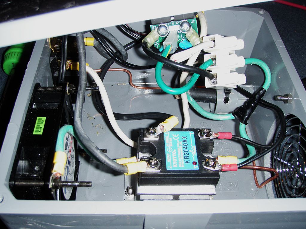
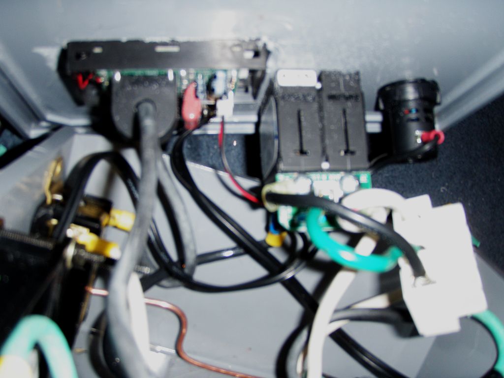
Tue Apr 22, 2014 2:20 pmby DRIFTER_016
Pretty much what I just put together.
I did use a 30A 220V panel mounted circuit breaker in place of the switch and installed a 220V power LED and digital V/A gauge.
But the rest is pretty much identical.
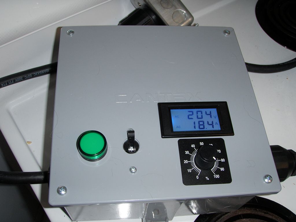
Some pics of my build.
100% power
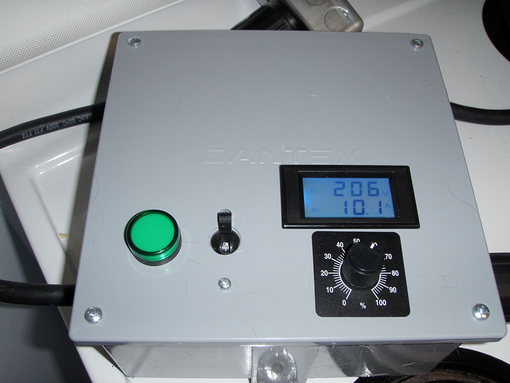
60% power.
Re: Punchy21's Controller Diagram for the CSVC
Posted:
Sun Nov 16, 2014 8:57 pmby Nays_Shine
I am currently buying a bunch of parts to build a voltage controller for my boka. My old man will wire up as he is a qualified electrician (although he hasn't worked as a sparky for 40 years).
As I am just about to order some things, I was hoping someone maybe able to confirm that I have selected a suitable relay and pot. He lives a long way away, I will need to purchase as many parts as possible prior to him assembling. While he may have suggestions, I want to stear him down a path based on the lessons learnt from this site.
I will be controlling a single 2200w, 240v element.
Here are the items I am looking at:
Solid State Relay - SSR-25VA, 24-380V(AC), to suit 470-560k ohm
http://www.uxcell.com/24380v-25a-soid-s ... 45476.htmlPotentiometer - 470K Ohm, 2W
http://www.uxcell.com/replacement-6mm-s ... 78828.htmlI will get the old man to decide how to wire the fan, switches, fuse etc.
I have read a lot about this today and know that the pot needs to match the ssr, but many ssr,s dont list a wattage or else they state; 1/2w or 1/4w. Does this mean .5w .25w or anywhere in the 1 to - 4 watt range?
I really appreciate any advice you can give me on this. :-)
Re: Punchy21's Controller Diagram for the CSVC
Posted:
Sun Nov 16, 2014 9:46 pmby Sam.
There is really no need for voltage control with a boka mate, just run if flat stick and make sure you got enough RC power :handgestures-thumbupleft:
Also drop in the welcome centre and tell us about what you want to do, it gives everyone a better idea on how to help ;-)
Re: Punchy21's Controller Diagram for the CSVC
Posted:
Sun Nov 16, 2014 11:49 pmby Nays_Shine
Thanks for the response Sam. I have created a brief intro at the welcome section (it includes a photo of some shiny finished parts of my build. I have a experimented with a slight variation to the boka reducer cup build and am using a 2" column with a 3" condenser head. I will save that conversation for another thread!).
Back on topic, I actually have 2 x 2200w elements (each on their own separate 10amp circuit) and while I have a pretty decent sized 9.5mm condenser I suspect I will want to reduce some power at some stage during cuts (simply turning off one element would work, but I want MORE CONTROL!!!! hahaha). I still haven't done a run yet though, so I dont know how it is going to perform. The trouble I have had with selecting a potentiometer is knowing what the power(w) spec should be as the spec on the SSR can be confusing 1/2w, 1/4w etc.
I am very happy to not get a variable voltage controller built if it is not required! As always, any thoughts and input will be well received!
Re: Punchy21's Controller Diagram for the CSVC
Posted:
Mon Nov 17, 2014 9:22 amby Zak Griffin
I'd say you'll only need both elements on to heat up, then it will run just fine on one.


